Creating firmware and loading it on the microcontroller.
Introduction
Now that I understand the matrix, it is time to learn how to program the hardware. It’s still amazing to me that all the keyboard logic can be contained on a tiny microcontroller the size of two fingernails. All the rest of the keyboard bulk is just there for the convenience of the human who is switching connections on the microcontroller.
In this article I will describe all the steps for getting a basic working QMK image on the microcontroller. The final product will be a functioning ProMicro, programmed for a custom keyboard. I will describe this for an small imaginary numberpad.
Matrix design
I will create the ProMicro firmware for the following board. I will call this one the “Tinkpad”.
Assigning rows and columns is clear in this case, I just need to decide where to put the bigger keys that overlap 2 rows or columns. That can be done more or less arbitrary, as long as every key is assigned to exactly 1 row and exactly 1 column. I will use the following row and column assignments:
Install and configure QMK
I opted for the QMK firmware for controlling my keyboard. This is a widely used open source project, which can be found on qmk.fm. With QMK, an image for the controller is compiled on a PC, and then flashed to the microcontroller using a USB cable.
Use the appropriate installer for your operating system to install QMK on your PC. I run Linux and I installed from the repository of my distribution. After installing, run the following command and answer “y” to all questions to configure QMK on the PC.
qmk setup
This will create a large directory tee with configurations for a large number of keyboards.
Create a new keyboard coniguration
Run the following command and answer the questions:
qmk new-keyboard
In my case, I entered “tinkpad” for the keyboard name, selected “None of the above” as the default lay-out and “ProMicro” as the MCU. This will create a new directory in the QMK tree for the new keyboard configuratrion.
To make life a bit easier, now enter:
qmk config user.keyboard=tinkpad
qmk config user.keymap=default
This writes the settings to .config/qmk/qmk.ini in my home directory. With these set, the following qmk commands will execute for the “tinkpad:default” keyboard, without me having to specify that with every command.
In the QMK directory, under keyboards/tinkpad/, create 2 new files:
cd ~/qmk_firmware/keyboards/tinkpad
echo '#include "tinkpad.h"' > tinkpad.c
touch tinkpad.h
Configure keyboard
Now I have to configure three things:
- The pins on the ProMicro where the rows and columns connect
- The row/column intersections that have a key
- The keystrokes that should me mapped to each defined key
ProMicro pinout
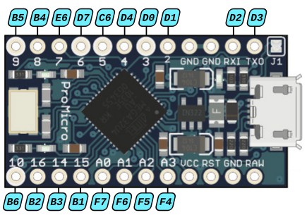
In the config.h file the pin numbers where the rows and columns connect need to be specified. The codes to use in this file are not the pin numbers printed on the ProMicro! Instead, these are the pin numbers of the ATmega32U4 controller on the ProMicro. I used the following image to select the codes to be used, the ATmega32U4 codes for each pin on the ProMicro are in the blue labels. Pins without a label have a specific function and cannot be used for the keyboard:

Assigning a pin to a row or column is arbitrary. I chose to assign the rows to the top pins and the columns to the bottom pins. I specify this as follows in the config.h file (add under the line #pragma once):
#define MATRIX_ROWS 4
#define MATRIX_COLS 4

/* Row number:             1   2   3   4  */
#define MATRIX_ROW_PINS { B5, B4, E6, D7 }

/* Column number:          1   2   3   4  */
#define MATRIX_COL_PINS { B6, B2, B3, B1 }
Putting keys on intersections
I defined a matrix with 4 rows x 4 columns = 16 intersections. Now I need to specify on which of the intersections there is a keyboard switch. Some intersections will not have a key. For instance, on the Tinkpad there is no key in the last column of row 2. This is defined as follows in tinkpad.h (including the blank line at the end!):
#define ___ KC_NO

#define KEYMAP( \
      K00, K01, K02, K03, \
      K10, K11, K12,      \
      K20, K21, K22,      \
      K30,      K32, K33  \
) { \
    { K00, K01, K02, K03 }, \
    { K10, K11, K12, ___ }, \
    { K20, K21, K22, ___ }, \
    { K30, ___, K32, K33 }, \
}
The second group of codes (the 4 entries between the curly braces) defines the four rows on the keyboard. Each entry on a line is a key in that row. If there is no key at a certain location of the row, I enter three underscores.
The first group of codes in the keymap (between the round braces) defines all keys that are on the keyboard. In this sequence, I just leave a gap if no key is present.
Assign keystrokes
The final step of the configuration is assigning keystrokes to the keys. This is done in the keymap.c file in the keymaps/default/ directory. Replace the contents of this file with:
#include QMK_KEYBOARD_H

const uint16_t PROGMEM keymaps[][MATRIX_ROWS][MATRIX_COLS] = {
    KEYMAP(
        KC_7,   KC_8,   KC_9,    KC_PSLS,
        KC_4,   KC_5,   KC_6,
        KC_1,   KC_2,   KC_3,
        KC_0,           KC_PDOT, KC_PENT
    )
};
The “KC_” constants define what keystroke should be sent when that key is pressed. KC_7 is the “7” key. Available constants can be found in the QMK documentation.
Compile the firmware
Configuration is all done! To compile the firmware, I enter:
qmk compile
This shows a lot of logging, each line ending with a green [OK] (or maybe a warning). The last lines read:
Copying tinkpad_default.hex to qmk_firmware folder                                                  [OK]
Checking file size of tinkpad_default.hex                                                           [OK]
 * The firmware size is fine - 15494/28672 (54%, 13178 bytes free)
In the ~/qmk_firmware/ directory there is now a file tinkpad_default.hex. This is the end result of all my efforts so far and this is the file that needs to be flashed to the ProMicro
Flash the firmware
To flash the firmware, I connect the ProMicro to my PC and enter the following command (note: Linux users need to be member of the groups “tty” and “dialout” to be able to flash the controller):
qmk flash
The following message is shown:
Waiting for USB serial port - reset your controller now (Ctrl+C to cancel)....
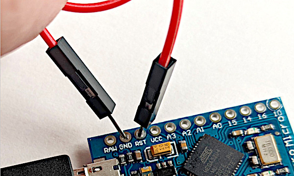
The PC is waiting for a reset on the ProMicro. To perform the reset, I use a wire and briefly connect the hole marked “RST” to the hole marked “GND” next to it.

Immediately, the flashing process continues on the PC and, when done, shows the message avrdude done. Thank you..
Test the firmware
To test the firmware, I connect the ProMicro to my PC and open a text editor. I now need to connect a row and a column. I insert one end of a wire in the hole marked “9” on the ProMicro. This is the pin for row 1 of the matrix. Now I tap the other end of the wire on the hole marked “10”. This is the pin for column 1 of the matrix. The text editor registers a “7” keystroke, which is the key on row 1 and column 1. Repeat for other keys, e.g. connecting pin “7” (row 3) and “16” (column 2) will register as keystroke “2”.
And that is it, a functioning keyboard on the ProMicro!