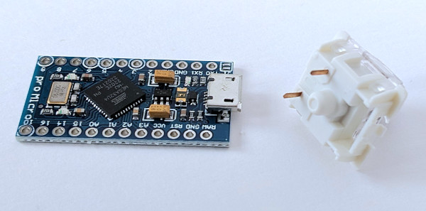
Creating complete keyboards without the need for an excessive amount of connections.
Introduction
Custom built keyboards are controlled with a microcontroller, usually an arduino or similar board. The round copper connectors at the edge of the microcontroller are called “pins”. The controller can detect when there is a connection between two pins, or between a pin and “ground”. This is than translated to the correct keystroke on the USB port of the controller. The number of pins on a controller is limited though.

The ProMicro pictured above has 24 pins, but only 18 pins are available to interface with a keyboard. if we wired the keys straight to a dedicated controller pin, only 18 keys can be controlled before we run out of pins on the ProMicro.
Example
As an example, imagine we want to build a tiny controller pad for playing games. The board contains 4 directional buttons, a button for firing the weapon and a quick save button:
If we were to connect every pin of the switches on this pad directly to a controller pin, we would need 12 pins on the controller. Another option is to connect the second pin of every switch to “ground”, than we need 6 pins.
Since we have 18 pins available, direct wiring is possible for this small board. For larger boards, the limit is quickly reached though. Using the “Keyboard Matrix”, a lot fewer connections are necessary. If the matrix layout is used for this small board, we only need 5 pins on the controller instead of 6. This may seem like a small insignificant, but the difference quickly gets larger when the keyboard gets larger.
Matrix solution
The matrix solution assigns a row and a column to every key. Every key has two pins, one pin is connected to a row wire and the other pin is connected to a column wire. In a fast rotating sequence the controller puts a signal on the column wires, one column at a time, and listens at the row wires if the signal is seen there.
The illustration below shows this setup. The yellow path marks the connection that is created when the “Fire” button is pressed, closing a path between column 3 and row 1. When the microcontroller puts a signal on column 3, it will detect this signal coming back on row 1. The key on the intersection of column 3 and row 1 is “Fire”, so the “Fire” keypress is sent to the USB port.
The basic matrix setup works well most of the time, but fails in certain conditions when multiple keys are pressed simultaneously.
Key rollover problem
Pressing multiple keys simultaneously is called “key rollover”. The basic matrix solution can not handle all situations. Simple situations do not cause problems however. Imagine the previous example with the fire button pressed, but the player now also starts moving forward. The signal on column 3 is seen back on row 1, which is the “Fire” button. The signal on column 2 is seen on row 1, the “Fwd” button. The basic matrix can handle this:
A problem scenario can occur when a third button is pressed. For example: while still moving forward and firing, the player now also turns right. The controller puts a signal on column 2 and checks which rows light up. Only row 1 should see the signal, since “Fwd” is the only key pressed in column 2. Row 2 lights up as well though, incorrectly indicating that the “Back” button is also pressed:
This problem is caused because the signal on row 1 leaks into column 3 through the “Fire” key. The signal is then passed to row 2 because the “Right” key is pressed.
n-Key rollover solution
Being able to press any combination of buttons on a keyboard simultaneously without the controller detecting ghost key presses is called “n-Key rollover”. This can be achieved with a matrix solution by adding a small modification.
A diode is added to every connection between a switch and the row wire. A diode is an electronic component that allows current to flow in one direction, but blocks the current that is coming from the other direction. Suitable diodes for a keyboard are tiny and dirt cheap.

The illustration below shows this configuration. With the same 3 keys pressed as the previous example, the signal from column 1 can pass the diode on the “Fwd” switch. For the diode on the “Fire” button however, the signal is approaching the diode from the other direction and is blocked, preventing the signal from reaching column 3.
Conclusion
Building a keyboard with a matrix layout reduces the amount of internal wiring. The matrix layout also reduces the number of required connections on the controller. To avoid problems with simultaneous key presses diodes need to be added to the internal wiring.