Starting the construction of my first custom mechanical keyboard.
Introduction
With the logical heart of the Tinkboard Zero configured, it is now time to connect the programmed microcontroller to a bunch of keyboard switches. This article is a photographic report of the building process, with explanation of the steps and the decisions I made.
Ordering the parts
These are the base components for the Tinkboard Zero. All standard off the shelf parts, except for the plate, which was ordered from a laser cutting service. Missing in this image are the stabilizers, which I ordered later.

The plate was build to order for me. Most laser cutting service providers accept SVG files as input, which can be generated using the JSON file from Keyboard Layout Editor. To generate an SVG file for your keyboard, head over to builder.swillkb.com and paste the JSON text there to generate the SVG file. Usually, select “MX” switch type and “Cherry only” stabilizer type. I also selected the “Poker 60%” case type and 2.5mm hole size, since my keyboard case has the Poker mounting holes.
Important, and I got this wrong, check at your laser cutting service what the “Kerf” is. Kerf is the width of the material removed by a cutting tool. If you specify 0 (the default), all slots in the plate will be slightly too large. Ideally the plate should be 1.5mm thick. Most materials will do, I selected “POM” because that was the only material available in 1.5mm.
I had a very hard time finding out which diodes to use. Ironically, this is such common knowledge that it is hardly ever specified. Anyway, these are “1N4148” diodes.
Switches
First step: click (and I use that term “loosely”, pun intended) the switches in the front side of the plate.

Now turn the plate over and put a hotswap socket on the back of every switch.
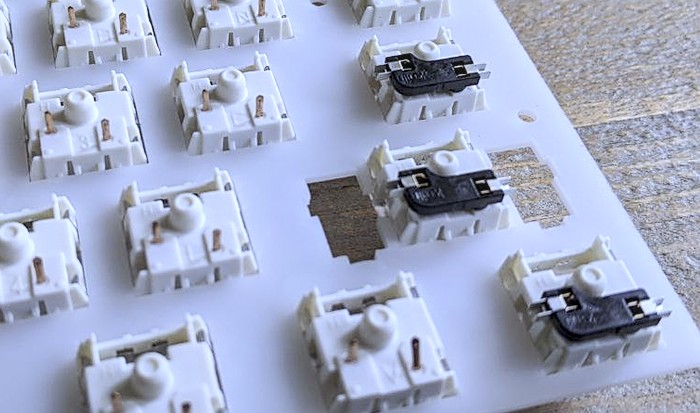
Hotswap sockets are usually soldered on the back of a PCB. I am building what’s called a “handwired” keyboard where you solder wires to the switches. Instead of soldering directly to the switches, I put a hotswap socket on every switch and solder to the socket. This way I can still change the switches without having to desolder them.
Rows
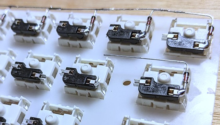
I first create the row connections by soldering one leg of a diode to a hotswap socket and folding the other leg over to the next switch. Here it can be soldered to the next diode. Take care of the correct direction of the diode, in my case the black ribbon points away from the switch. Both directions are fine as long as they are all the same but “Column to row” is the QMK default. I keep an eye on the row layout I programmed (mirrored, I am working from the back now!) and duplicate this with the diodes.
Columns
I stripped a couple of network cables to create the columns on the other pins of the hotswap sockets (again, mirrored!). Network cables contain 8 color coded wires, which makes following the connections a bit easier. Not ideal for soldering though, the insulation on those wires is not very heat resistant.
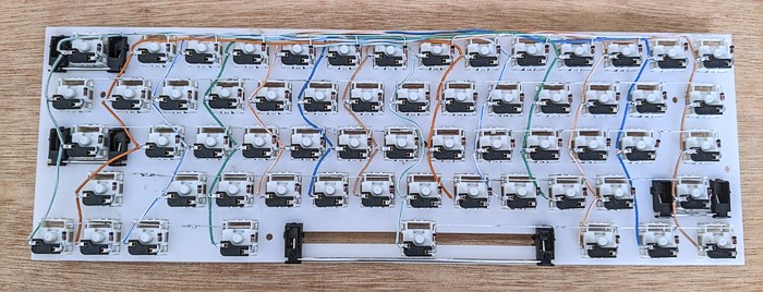
Notice how the wires from the left loop over the top and cross back down a second column. This way they connect and form one column.
ProMicro
Now I need to connect every row and every column to the ProMicro. I threaded some wires through the gaps between the switches, connect one end to a row/column and the other end to the designated pin on the ProMicro.
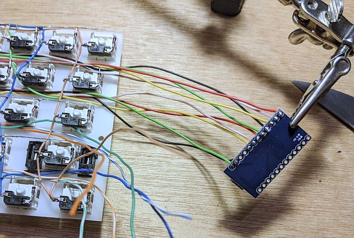
With everything now connected, I plug one end of a USB cable into the ProMicro and the other end into my laptop and check. Amazingly, it all works!

So finish off: put on the keycaps, all done!
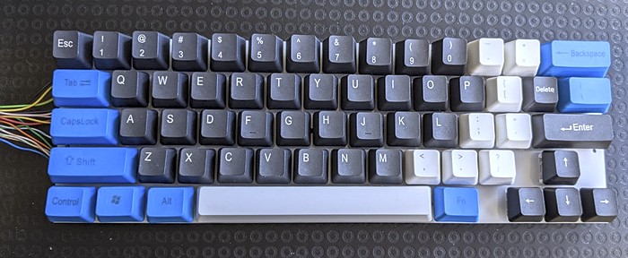
OK, that is not finished at all. The ProMicro is dangling from the side and the back consists of exposed wires. Everything still needs to be packaged into the keyboard case. I did not really plan ahead that far. No way I can get the ProMicro neatly into the case with the short wires I used. Let’s call it a proof of concept for now and complete the construction later.